Help:DataVisualizationInCytoscape
From WikiPathways
(→Data import) |
(→Viewing data on pathways) |
||
| Line 110: | Line 110: | ||
= Viewing data on pathways = | = Viewing data on pathways = | ||
| - | + | The data and pathways are now both imported and linked and we can visualize the data on the pathways. For this tutorial, we will create a color scheme for all significant nodes, based on ANOVA values for a comparison across three experimental groups. | |
| - | + | * In the '''Control Panel''' on the left side of Cytoscape, select the '''Style''' tab. | |
| + | * In the list of '''Properties''' click on the triangle next to '''Fill Color''' to expand. | ||
| + | * Click on '''Fill Color''' next to Column. In the drop-down, select '''ANOVA''' to select the ANOVA column from the data. | ||
| + | * Under '''MappingType''', select '''Continous Mapping'''. | ||
| + | |||
| + | [Image] | ||
| + | |||
| + | * Double-click on the default black and white continuum to customize it. | ||
| + | |||
| + | [Image] | ||
| + | |||
| + | * First, set the min/max values by clicking the '''Set Min and Max...''' button. Set Min to 0 and Max to 1. | ||
| + | * Next, double-click the large triangle at the left and select a blue color. Repeat with the smaller triangle handle right next to it. | ||
| + | * Move the smaller left-most handle to the right, to the 0.05 position. Once the handle is selected, its position can be set in the '''Handle Position''' field. | ||
| + | * For the large right-most triangle, set the color to a pale gray color. | ||
| + | * Next, select the small right-most triangle and click '''Delete''''. | ||
| + | |||
| + | [Image] | ||
| + | |||
| + | You now have a color scheme where nodes with an ANOVA value of 0.05 or below is colored blue, and all other measured nodes are colored gray. Nodes that are not found will simply be white. | ||
| + | |||
| + | [Image] | ||
Revision as of 22:06, 11 January 2016
UNDER CONSTRUCTION
This tutorial describes how to visualize experimental data on WikiPathways in Cytoscape. After importing the data, it is mapped to standard identifiers using BridgeDb. A visual style is created, and the data is visualized on pathways imported from WikiPathways.
Contents |
Installation
Cytoscape
- Download Cytoscape here: http://www.cytoscape.org/.
- Launch Cytoscape
Cytoscape Apps
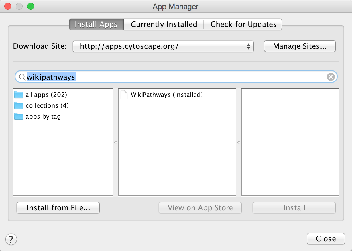
- In Cytoscape, open the App Manager under Apps > App Manager.
- In the search field, type WikiPathways to search for the WikiPathways app. In the search results, select the WikiPathways app and click Install.
- Next, find and install the BridgeDb app in the same way. When the installation is complete, click Close to exit the App Manager.
Alternatively, Cytoscape apps can be installed directly from the Cytoscape App Store. If Cytoscape is open on your computer, you can click Install on the relevant app page, and the app will install.
Data import and mapping
Download the data
For this tutorial, we will use an example dataset describing intestinal changes in response to fasting. The data is in the form of a text file.
The experimental data for this tutorial can be found here: Starvation_dataset_trans.txt.
Open pathways
Based on over-representation analysis, two pathways have been identified as significant for this dataset. To start, we will open these pathways.
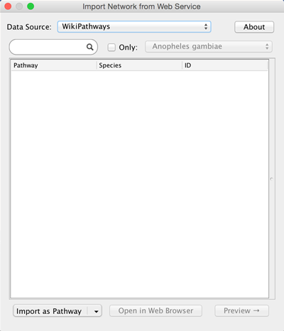
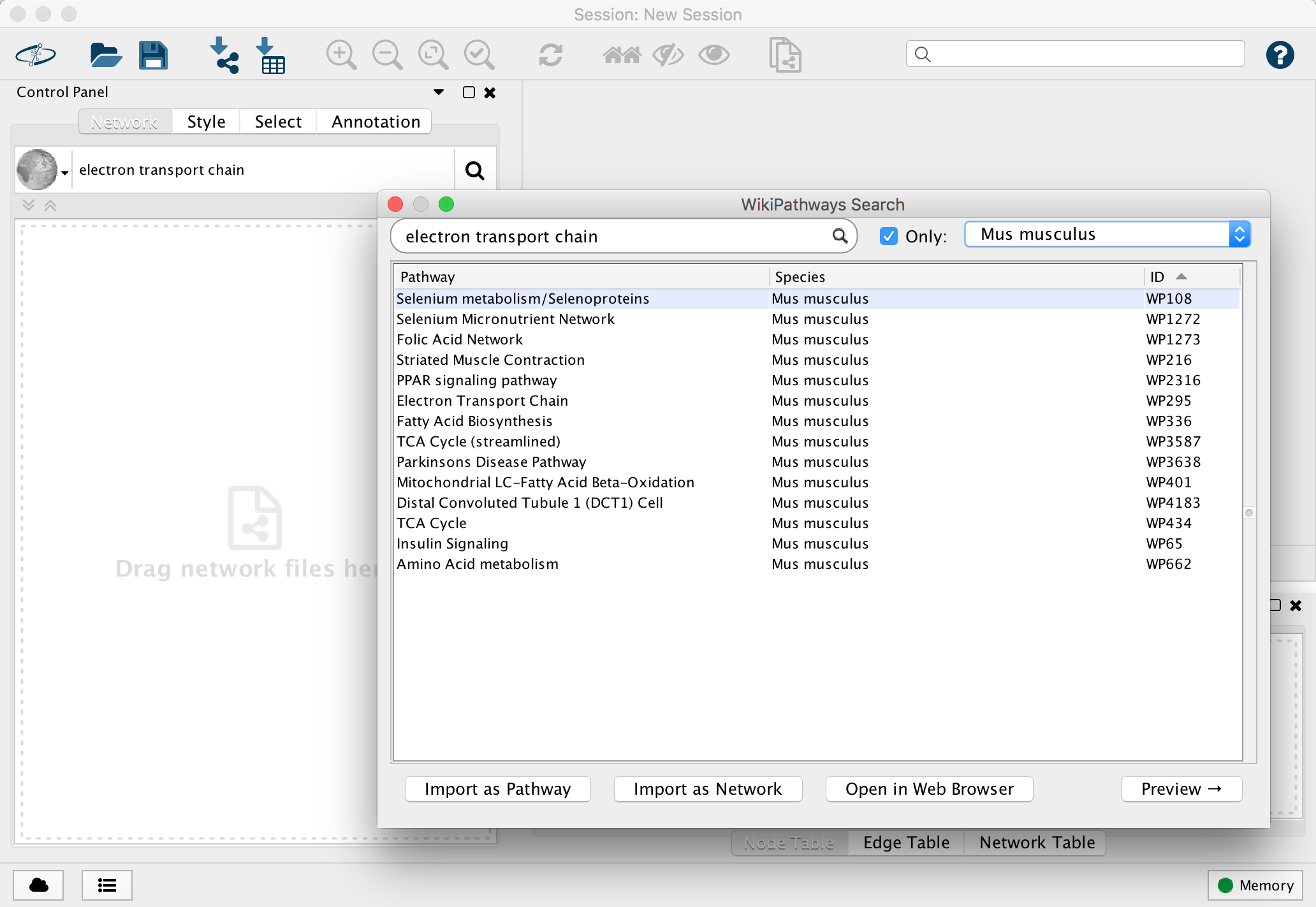
- Go to File > Import > Network > Public Databases.... In the Data Source drop-down, select WikiPathways.
- Check the box for Only and select Mus musculus in the species drop-down.
- In the search field, type in Electron Transport Chain. Click Enter to search.
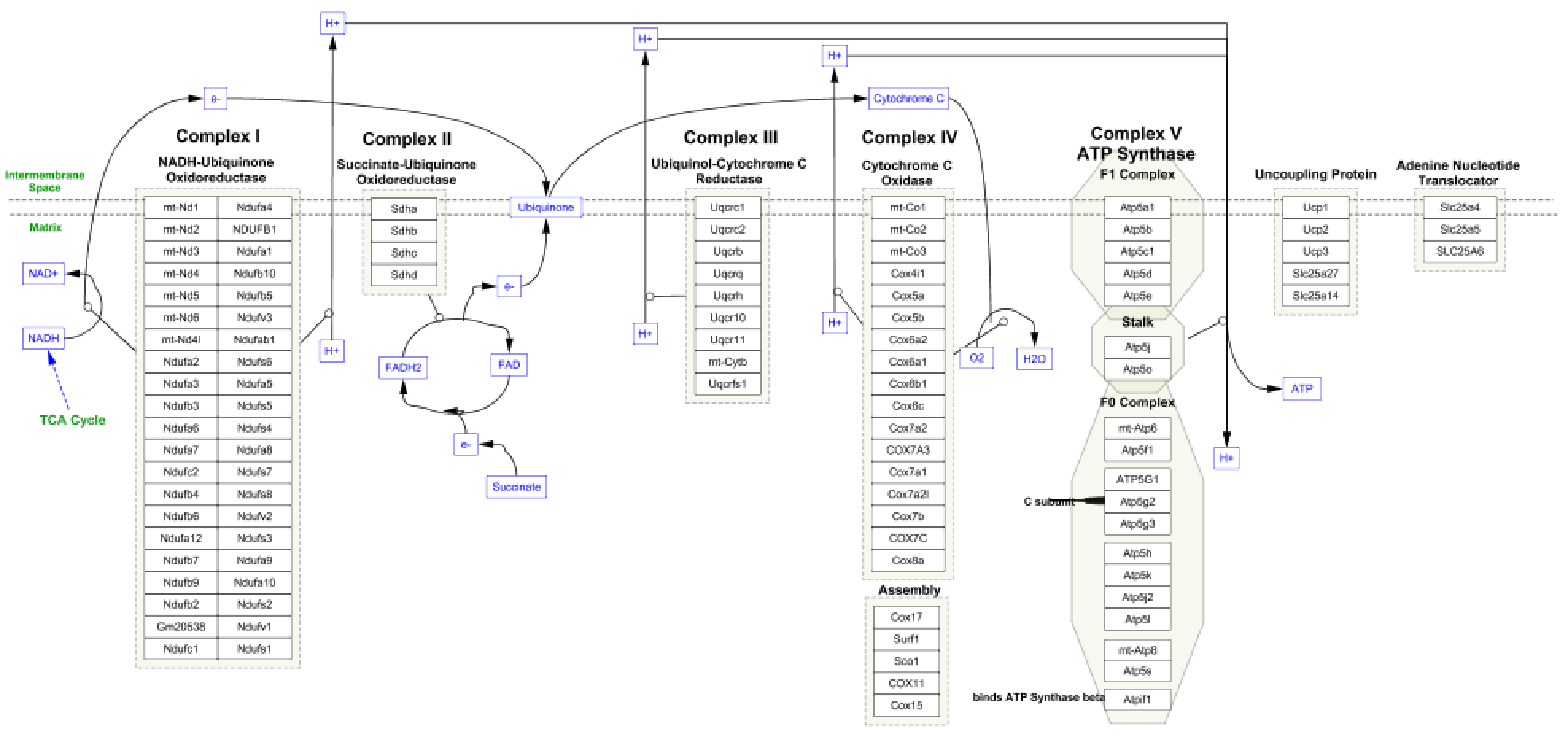
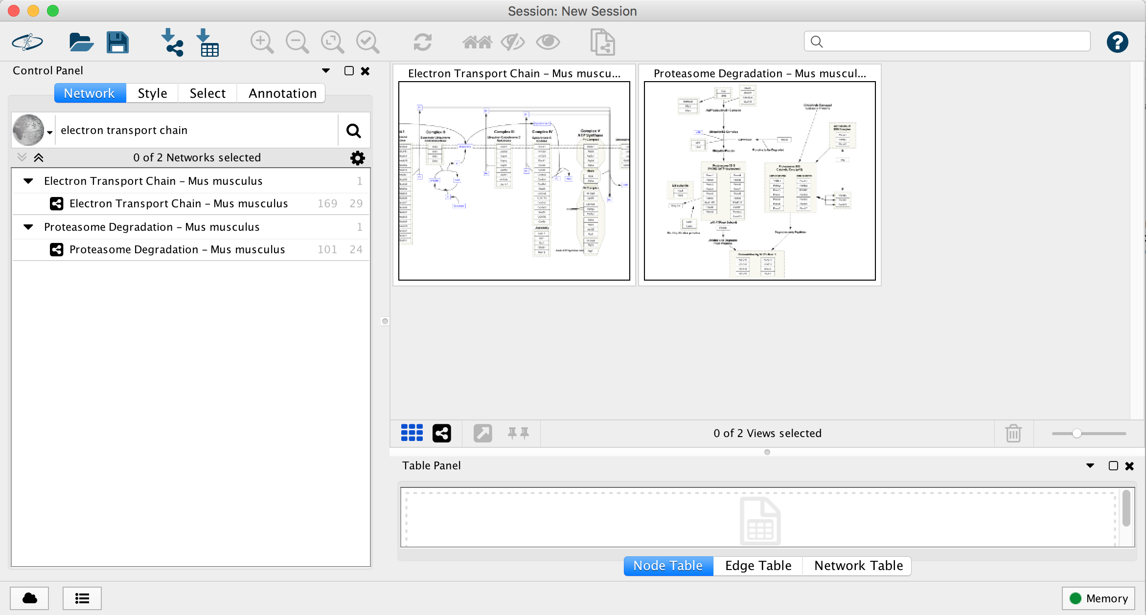
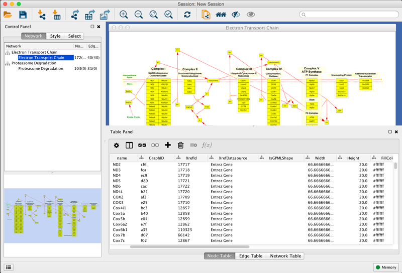
- In the pathway results, select the Electron Transport Chain and either double-click on the entry to open, or click ont he Import as Pathway button at the bottom right. Once opened, the pathway should look like this:
- Repeat the steps above to import the Proteasome degradation pathway.
- You should now have both pathways open in Cytoscape:
Identifier mapping with BridgeDb
Since the data is annotated with Ensembl identifiers and the pathways have a mix of identifiers, the pathways need to be mapped to Ensembl before the data can be visualized. The BridgeDb app does exactly this, given a mapping file. Before performing the mapping, we have to import the appropriate mapping file to BridegDb.
- Open the BridgeDb app under Apps > BridegDb > Manage ID Mapping Resources.
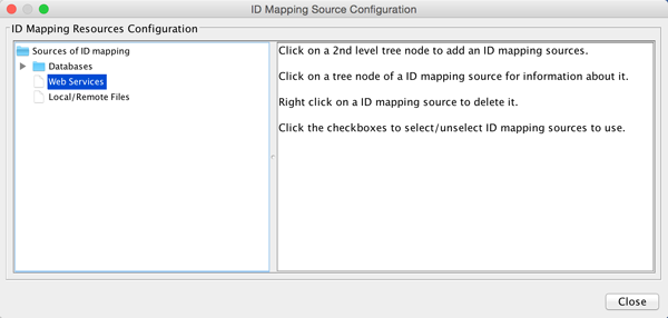
BridgeDb works with mapping information from various sources. For example, y ou can either download a database here, and after extracting it you can select it under Databases in the ID Mapping Resouces Configuration interface. You can also supply a local or remote mapping file. For this tutorial, we will use Web Services for the mappings.
- Click on the Web Services entry in the list of ID mapping sources.
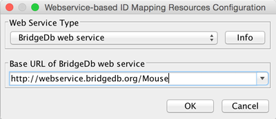
- In the Webservice-based ID Mapping Resources Configuration interface, select BridegDb web service in the drop-down.
- In the Base URL of BridgeDb web service drop-down, select the entry for mouse. Click OK to continue.
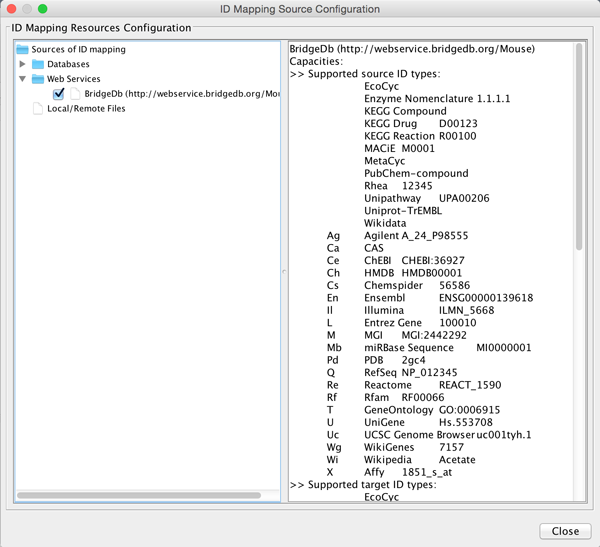
You will see a listing of supported ID systems. We are now ready to perform the mapping.
- Close the ID Mapping Source Configuration interface.
We are now ready to map the identifiers from the pathways to Ensembl. BridgeDb works best when you know the type of identifier to map from (Source).
- To find out which identifier type(s) is used in your pathway, first select all nodes on the pathway by clicking and dragging to select the entire pathway. Selected nodes will turn yellow.
- Immediately below the network view in Cytoscape is the Table Panel. Expand the table either by clicking dragging on the table border, or by click on the Float Window icon on the right end of the Table Panel border.
- The identifier types for data nodes are listed in the XrefDatasource column. The 4 pathways in this tutorial are annotated with a mix of Entrez Gene, MGI and Ensembl identifiers.
- With one of the networks selected, go to Apps > BridegDb > Map Identifiers.
- In the BridgeDb interface, open the drop-down under Source ID Type(s), and select Ensembl, Entrez Gene and MGI in the list of identifier types.
- In the Source Column in Node Table, select XrefId, which is the column that contains the identifier for WikiPathways.
- In the Target ID Type, select Ensembl. The Target Column in Node Table will default to Ensembl, which will be a new column in the 'Table Panel for the pathway.
- Finally, in the All Target ID(s) or First Only? drop-down, select Keep the first target ID only.
The interface should now look like this:
- Click OK to run the mapping. When the mapping is complete, you will get a message stating how many identifiers were converted, and a question about running additional mapping. Click No to close BridgeDb.
- Repeat the mapping process with the Urea cycle pathway.
Data import
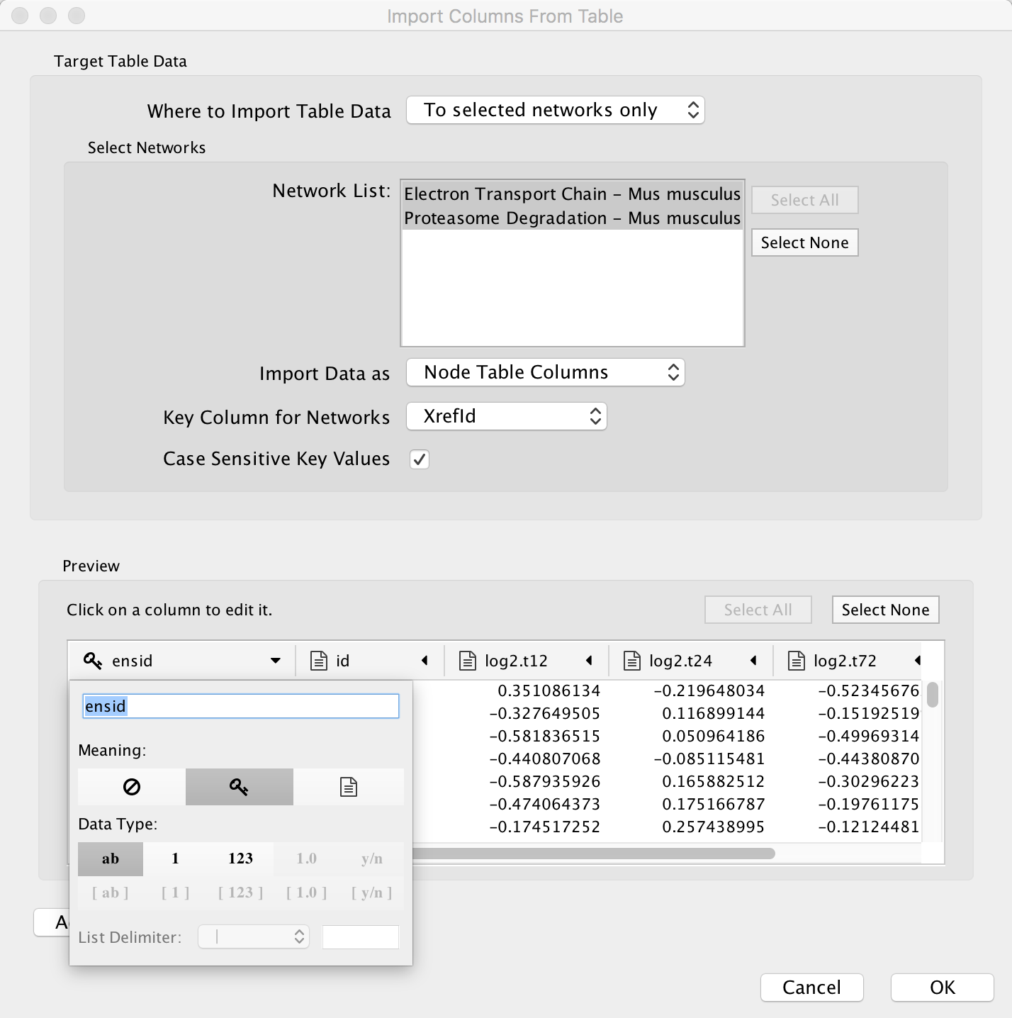
- To import the experimental data, select File > Import > Table > File.... Select the starvation_dataset_trans.txt file and click Open.
- Under Where to Import Table Data, choose To selected networks only.
- To select both pathways, click the Select All button.
- Under Key Column for Networks, select Ensembl. This is the column created during BridgeDb mapping.
- In the Preview section, click the expand symbol at the top of the ensid column. This will open an interface where you can define the details of the column, such as data type etc.
- For the purposes of this tutorial, click the key symbol. This defines the ensid column as being the key column, which will be used to link the data to the pathways.
- Click OK to import the data.
Viewing data on pathways
The data and pathways are now both imported and linked and we can visualize the data on the pathways. For this tutorial, we will create a color scheme for all significant nodes, based on ANOVA values for a comparison across three experimental groups.
- In the Control Panel on the left side of Cytoscape, select the Style tab.
- In the list of Properties click on the triangle next to Fill Color to expand.
- Click on Fill Color next to Column. In the drop-down, select ANOVA to select the ANOVA column from the data.
- Under MappingType, select Continous Mapping.
[Image]
- Double-click on the default black and white continuum to customize it.
[Image]
- First, set the min/max values by clicking the Set Min and Max... button. Set Min to 0 and Max to 1.
- Next, double-click the large triangle at the left and select a blue color. Repeat with the smaller triangle handle right next to it.
- Move the smaller left-most handle to the right, to the 0.05 position. Once the handle is selected, its position can be set in the Handle Position field.
- For the large right-most triangle, set the color to a pale gray color.
- Next, select the small right-most triangle and click Delete'.
[Image]
You now have a color scheme where nodes with an ANOVA value of 0.05 or below is colored blue, and all other measured nodes are colored gray. Nodes that are not found will simply be white.
[Image]
